
Proper roof system design involves managing the water a roof system is expected to encounter during its service life, and multiple trades and disciplines are involved in the task.
If you are responsible for the design or installation of roof drains, you should be aware how guidelines and requirements differ.
Positive drainage
Positive drainage provisions for thoroughly draining a roof area include the correct number, sizes and placement of roof drains, scuppers or gutters, as well as design of drainage crickets and saddles with sufficiently sloped valleys to assist with drainage. A general rule of thumb for designing sufficiently sloping saddles and crickets is the saddle and cricket material should be twice the slope of the adjacent roof field. This generally will keep water from remaining on the surface of a cricket and/or saddle.
However, for cricket or saddle valleys to drain, NRCA recommends designers recognize the importance of cricket geometry and, specifically, valley slope. Refer to The NRCA Roofing Manual: Membrane Roof Systems—2023 Section 4.15—Tapered Insulation for information regarding the design and use of tapered insulation (available at shop.nrca.net).
Drains should be located at low points in a roof (points of maximum deck deflection) not at columns or bearing walls (points of minimum deflection). When a design dictates drains be placed adjacent to column or bearing walls, the designer should ensure positive drainage.
International Plumbing Code®
The 2024 IPC provides requirements for the proper design of drainage for roof systems.
To appropriately size conductors, leaders and storm drains as required in IPC, Section 1106.1—General Requirements for Stormwater Drainage System Sizing, plumbing and mechanical engineers use the 100-year hourly rainfall rate for a building’s specific area to determine the maximum anticipated ponding at the location of the roof drain.
The maximum anticipated ponding is determined from the geometry of a roof system’s slopes around the drain, as well as the published roof drain flow rate based on the head of water above the roof drain.
This calculation is difficult because the flow rate through a roof drain is not constant as water depth changes. The more water arrives at a drain, the faster it exits. Finding the depth at which there is balance often requires iteration and is further complicated because more water at a drain also means more structural deflection in that area, which begets still more water and more iterations.
The maximum depth of water can be used to determine the maximum anticipated flow rate through the roof drain, which needs to be considered for the proper selection of leaders, conductors and storm drains.
A study conducted in 2012 by the American Society of Plumbing Engineers Research Foundation can help explain why the maximum anticipated flow rate through the roof drain needs to be considered for the proper selection of leaders, conductors and storm drains. The study found roof drains affect how well water drains from a roof. The following summarizes the findings:
- Roofs drain water better through roof drains versus just a hole.
- The flow rate through a given roof drain is directly correlated with and depends greatly on the depth of water at the drain.
- Flow rates through similar roof drains can vary dramatically from one another.
To avoid installing a roof drain that has a maximum anticipated flow rate exceeding the capacity of the leaders they are connected to, the leader size is chosen to handle the roof drain flow rate at the maximum ponding depth not the other way around.
The secondary drainage is determined in much the same way but assumes all primary roof drainage means are blocked.
The 2024 IPC provides 100-year, one-hour rainfall maps that are used along with the roof layout and roof drain manufacturer’s published flow rates to determine the maximum anticipated flow rate through that drain. This number then can be used with IPC Table 1106.2 to select an appropriate storm drainpipe size.
Uniform Plumbing Code®
The primary model code used in some states and jurisdictions is the International Association of Plumbing and Mechanical Officials 2024 Uniform Plumbing Code. This provides a different set of requirements that has designers arriving at drain size in a totally different way.
In many ways, the UPC is simpler and more conservative. Determining drain size requires only two things: rainfall rate and horizontal projected roof area. First, you determine how many square feet on a roof a specific drain services based on the slope and taper layout using only the area’s horizontal dimensions. Then, use that value and the desired rainfall rate to find a corresponding drain, leader or pipe size found in UPC’s Chapter 11—Storm Drainage, Table 1103.1.
If the desired rainfall rate is not in the table, it can be linearly interpolated or calculated as a factor in the “1 inch per hour column.” The other detail this code takes into consideration is the inclusion of side walls draining onto a roof into the calculation of horizontal projected roof areas. Depending on the layout of the sidewall or walls, up to 50% of the vertical area of the wall is added to the roof area to account for water that hits the wall and ends up on the roof where it would otherwise not have fallen.
There is no consideration for the manufacturers’ published roof drain flow rate information at different heads of water and assumes a consistent 1 1/2-inch head of water at drains. This method provides less flexibility for the designer to get precise about anticipated ponding and flow rate and typically leads to larger pipe sizing.
If you are responsible for the design or installation of roof drains, you should be aware how guidelines and requirements differ
International Building Code®
Separately, the structure needs to be designed to withstand the weight of water. The 2024 IBC Section C1611.1—Design Rain Loads outlines the structural design requirements for rain loads that are based on the requirements of Chapter 8—Rain Loads of ASCE 7-22, “Minimum Design Loads and Associated Criteria for Buildings and Other Structures.”
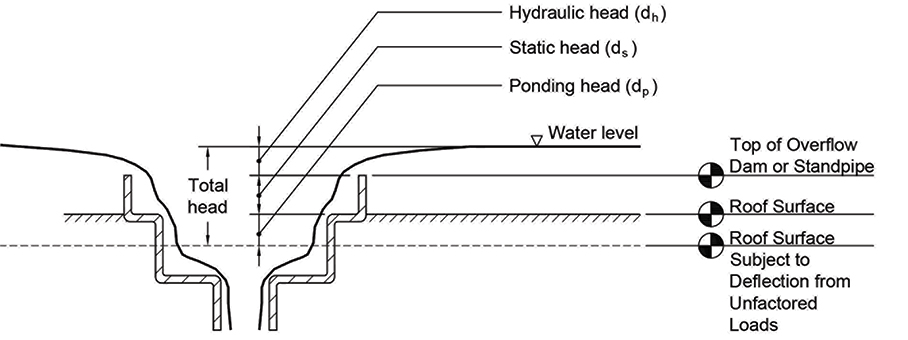
The load is split into three factors. These factors are combined resulting in rain load R measured in pounds per square foot (see figure).
R = 5.2(ds + dh + dp)
ds = Static head: The depth of water in inches on the undeflected roof up to the inlet of the secondary drainage system for structural loading in inches
dh = Hydraulic head: The depth of water in inches on the undeflected roof above the inlet of the secondary drainage system for structural loading required to achieve the design flow
dp = Ponding head: The depth of water in inches as a result of deflections of the roof subjected to unfactored rain load and unfactored dead load
5.2 = The weight in pounds of 1 square foot of water at a depth of 1 inch
The way the depth of water above the secondary drainage system is calculated is based on ASCE 7, which requires using the rainfall intensity of a 15-minute duration storm with a return period of 100, 200 or 500 years depending on the risk category of the building.
This means a drainage system for a Risk Category IV building strictly following the IPC may be sized for a one-hour duration, 100-year rain and then the structural design would base calculations from those drain and pipe sizes but use the much more conservative 15-minute, 500-year rain, resulting in a potentially much larger hydraulic head because water would be arriving at the drain faster than it could leave.
This means design decisions for roof drains based on the IPC affect the design of the structure based on the IBC and vice versa. Conservative roof drain designs reduce the expected ponding and the structural requirements that come with the larger rain load. Less conservative structural design can mean more deflection and more water at roof drains, leading to larger drains and pipes required than the IPC.
Closing thoughts
Designers have a lot to consider and, in some cases, a range of options for proper selection of roof drains and pipes:
- These decisions cannot be made in a vacuum as they can be consequential for other design decisions like structural member sizing.
- In many cases, proper roof drain selection relies on roof drain manufacturers providing published flow rate data at different heads of water.
- When contractors are responsible for the installation of the roof drain, it is important to use the exact drain specified and set it as close to the design height as feasible.
- Membranes and target sheets should be cut per the manufacturer’s installation instructions so as not to limit flow rate through the drain.

KURT FESTER, BECxP, CxA+BE
A director of technical services
NRCA