Proper wind design of roof systems is a relatively complex, sometimes misunderstood undertaking; however, it is essential for proper roof system performance. It is important to know the requirements and process for proper wind design of most low-slope roof systems.
Code compliance
The International Building Code® requires design wind loads be determined according the ASCE 7, “Minimum Design Loads and Associated Criteria for Buildings and Other Structures.” IBC 2024’s Section 1609.1.1-Determination of Wind Loads indicates wind loads for buildings be determined in accordance with ASCE 7-22’s Chapters 26 to 30. Section 1609.5-Tornado Loads indicates Risk Category III and IV buildings in the tornado-prone region east of the Rocky Mountains also be in accordance with ASCE 7-24’s Chapter 32-Tornado Loads.
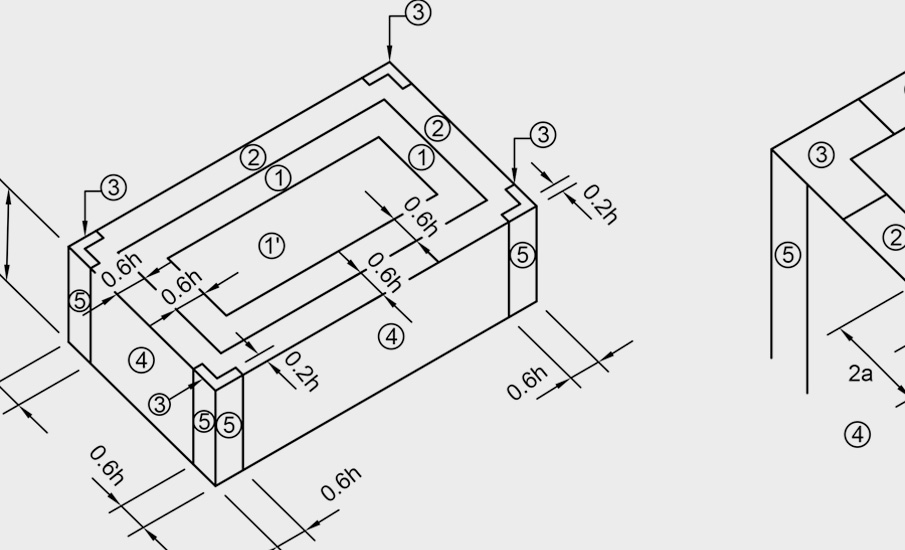
IBC Section 1603.3 requires construction documents show wind and tornado design data, including the basic wind speed (V), tornado speed (VT), allowable stress wind speed (VASD), and design wind pressures and their applicable zones with dimensions.
IBC Section 1504.4 requires built-up, polymer-modified bitumen, adhered or mechanically attached single-ply and metal panel roof systems over roof decks be tested for wind resistance in accordance with FM 4474, “American National Standard for Evaluating the Simulated Wind Uplift Resistance of Roof Assemblies Using Static Positive and/or Negative Differential Pressures;” UL 580, “Tests for Uplift Resistance of Roof Assemblies;” or UL 1897, “Uplift Tests for Roof Covering Systems.” The code does not require this testing be conducted at FM or UL Solutions; testing at other recognized laboratories using FM or UL test methods is acceptable.
Structural metal panel roof systems without roof decks must be tested in accordance with FM 4474 or ASTM E1592, “Test Method for Structural Performance of Sheet Metal Roof and Siding Systems by Uniform Static Air Pressure Difference.” Through-fastened, structural metal panel roof systems must be tested in accordance with ASTM E1592, FM 4474 or UL 580.
Ballasted single-ply membrane roof systems are not required to be tested. They must be designed in accordance with ANSI/SPRI RP-4, “Wind Design Standard for Ballasted Single-ply Roofing Systems.”
ASCE 7-22
ASCE 7-22 provides a recognized means for determining minimum loads, hazard levels, associated criteria and intended performance levels for buildings. Versions ASCE 7-10 through ASCE 7-22 use the ultimate strength design method. The ultimate strength design method results in higher loads than the earlier allowable stress design method used in ASCE 7-05 and earlier editions.
When it comes to determining wind loads on roof systems, ASCE 7’s Chapter 26-Wind Loads: General Requirements, Chapter 30-Wind Loads: Components and Cladding and Chapter 32-Tornado Loads apply.
ASCE 7-22’s Chapter 26 provides definitions; basic wind speed maps; explanations of the necessary calculation variables; and the fundamental equation, Equation 26.10-1, for determining a building’s velocity pressure at a height above grade (qZ).
Using Chapter 30, qZ can be converted to a low-slope roof system’s field, perimeter and corner design wind pressures by applying external pressure coefficients (GCps). Chapter 30’s Part 1, Equation 30.3-1 and Figure 30.3-2A apply to enclosed, partially enclosed and partially open buildings with a mean roof height of 60 feet or less. Part 2, Equation 30.4-1 and Figure 30.4-1 apply to enclosed, partially enclosed and partially open buildings with a mean roof height greater than 60 feet. Part 3, Equation 30.5-1 and Figures 30.5-1 through 30.5-3 apply to open buildings of all heights.
Chapter 32’s tornado load provisions apply to Risk Category III and IV buildings located in the tornado-prone region, which is east of the Rocky Mountains.
Section 32.17 provides separate calculations based on tornado speeds for buildings with a mean roof height of 60 feet and less and for buildings taller than 60 feet. The chapter includes 16 tornado speed maps based on risk category and effective wind area. ASCE’s Wind Design Geodatabase also can be used to determine building-specific tornado wind speed.
If Chapter 32’s calculated tornado loads are greater than the calculated wind loads for a specific building, the higher tornado loads should be used for wind design purposes.
Did you know?
ASCE’s Wind Design Geodatabase, ascehazardtool.org, provides a web-based application alternative to using ASCE 7-22’s maps for determining the basic wind speed at a building’s specific address.
NRCA’s Roof Wind Designer provides a web-based application that provides project-specific design wind and tornado loads based on ASCE 7. Roof Wind Designer is accessible free of charge at roofwinddesigner.com.
Tested resistances
Code-approved testing agencies, such as FM and UL Solutions, provide uplift testing based on the code-prescribed test methods. Roof system manufacturers typically make the results of these tests available. FM Approvals makes the results of its testing available via its RoofNav application, roofnav.com. Similarly, UL makes its test results available on its UL Product iQ® application, which is accessible at productiq.ulprospector.com.
Designers aim to design roof systems to have a tested uplift greater than the highest design wind pressure, typically the perimeter or corner pressures.
FM Property Loss Prevention Data Sheet 1-29, “Roof Deck Securement and Above-Deck Components,” provides an alternative method, referred to as the prescriptive enhancement approach, to address higher design wind loads at roof perimeters and corners. With this approach, designers use a roof system with a tested uplift greater than the roof field pressure then enhance the roof system’s attachment at the roof area’s perimeter and corners. Perimeter attachment is increased by a minimum of 50%, and corner attachment is increased by at least two times.
Although FM 1-29’s prescriptive attachment approach often is used, IBC does not recognize it.
Also, designers typically apply an additional safety factor, which effectively reduces a roof system’s tested resistance to allowable capacity. For example, a minimum safety factor of 2.0 traditionally has been applied when using ASCE 7-05’s and previous editions allowable strength design method.
Using ASCE 7-22’s ultimate strength design method, a safety factor of 1.25 is equivalent to the 2.0 safety factor.
Additional guidance
Additional information about using ASCE 7-22 is available in the Commentary to ASCE 7-22. ASCE 7 and its commentary can be purchased from ASCE by accessing asce.org.
Also, Appendix 1-Wind Uplift in The NRCA Roofing Manual: Membrane Roof Systems—2023 provides additional information about proper wind design of roof systems. The manual also can be purchased at shop.nrca.net; NRCA members can download the manual free of charge.

MARK S. GRAHAM
Vice president of technical services
NRCA


